What about the future? What are the new applications? And can we really use this to communicate with exoplanets?
How can operators benefit from digital beamforming? What is the capacity gain and why does it work so much better?
Drilling into the hart of the matter for BeammWave! Digital beamforming – to-be-or-not-to-be?
Everything goes digital, why would beamforming be the only technology that does not?
What is mmWave and how do you do beamforming?
Wouldn’t 4G be enough for me? Is 5G just a hype to get me to upgrade and spend more?
The mmWave frequency range is highly suitable for sensing and radar purposes due to the short radio wavelength enabling localization and positioning in the mm to cm range. Joint sensing and communication is being discussed, where a communication system not only communicates but also senses the environment and basically uses mmWave radar for the detection and positioning of objects.
Traditionally when designing analog or hybrid beamforming solutions for mmWave the design has been targeting a single application. A certain antenna panel/array has been designed for a certain purpose, such as a handheld device, and if another mmWave transceiver architecture is needed for another application that needs more antennae, such as a fixed wireless access point, or a small base station, another larger antenna panel has typically needed to be designed.
The 5G-NR mmWave communication devices range from a simple IoT device, via smartphones and fixed wireless access points, to devices for non-terrestrial communication as well as base stations. Designing different antenna panels with analog beamforming solutions for each of these use cases comes with a cost.
It would be an advantage to develop a scalable beamforming solution covering several of the use cases above, thereby reducing the development cost and enabling innovation of potential not-yet-known applications (possibly having almost unlimited bandwidth) as is the case in the mmWave radio spectrum.
Fortunately a digital beamforming architecture where one integrates the radio transceiver (RF) chip and antenna in a single encapsulation has this scaling possibility. The radio chip comprises the analog front end radio components, including down and upconverters, taking the mmWave radio signal from mmWave radio frequency down to an analog baseband signal on the receiver side and converting the transmitted analog baseband signal to mmWave radio signals on the transmitter side. The analog baseband signals have a bandwidth corresponding to the 5G-NR mmWave bandwidth and therefore are in the range of 100-400 MHz, those signals being easy to route on the PCB to a digital baseband processor.
The above integrated antenna and RF chip, when combined with digital beamforming algorithms that are implemented in the digital baseband processor, can be tailored to a flexible amount of antennae. Thus a scalable, low cost mmWave implementation for various use cases can be achieved by just applying as many RF chips as are needed for the particular use case. For instance, if we consider a mmWave IoT device that is only transmitting a small amount of data over short ranges, then it may only need two RF chips, plus associated SW that handles beamforming, to be configured for connection to two antennae to create such a device.
A more complex use case relates to a mmWave smartphone implementation. This needs to solve the challenges associated with handheld devices (these have been discussed in previous posts) and therefore need a distributed antenna architecture with, say, 8-16 Antennas and RF chips, with the corresponding digital beamforming algorithms adapted to that amount of antennae. Considering even more complexity, such as a Fixed Wireless Access Point, then 32-64 RF chips may be needed so as to achieve the desired data rate (several Gb/s).
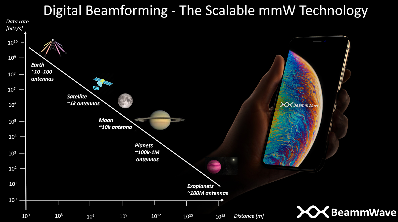
The same set of mmW RF chips are reused for all types of devices. However, in order to meet any requirements for higher transmitting power and better receiver sensitivity, typical for more advanced use cases, then these are solved by adding more RF chips. The level of scaling can also continue to base stations, devices used for non-terrestrial communications such as drones and aeroplanes (requiring 100+ antennae) and to devices communicating with satellites (1000+ antennae). One can even imagine extending the scaling idea of digital beamforming radio architectures to inter-planetary and interstellar communication, where the number of antennae in these cases need to be in the range of hundreds of thousands to hundreds of millions of antennae. However, there might be some challenges with the 5G latency requirements in the communication that need to be solved as well 
BeammWave develops a scalable digital beamforming architecture enabling the mmWave mass market on earth as well as in the sky.
We have in our previous posts shown the advantages with digital beamforming over analog beamforming from a performance point of view. Then one may ask; why hasn’t digital beamforming in mobile devices happened yet?
Well, if you ask people in the field, they will say that a digital approach has way to high power consumption due to the need of entire transceiver chain for all antennas whereas an analog approach only requires single transceiver chain due to that the beamforming is done in the analog domain at the front-end receiver using phase-shifters. Well, this might have been the truth in the past but let us check the case with the current state of the art technology.
Starting with the analog phase-shifters, which comprises switches and various physical routing of traces on the PCB used in order to make sure of coherent combining of the signal received or transmitted from the respective antenna. Passive phase shifters come with a loss of 8-10 dB to the already weak radio signal received by the antenna. That signal power loss needs to be compensated by a high gain Low Noise Amplifiers (LNA) on the receiver side and a high gain Power Amplifier (PA) design on the transmitter side. Such high gain high LNAs and PAs consume a significant part of the total power consumption in the radio receiver.
A digital beamforming architecture performs the combining in the digital domain and therefore the LNA and PA design can be more relaxed for digital architectures saving significant amounts of the power consumption.
Another important factor is that it is commonly believed that the analog-to digital and digital-to analog converters (ADC,DAC) need to be designed in the same way for both digital and analog beamforming, and since a digital beamforming requires an ADC/DAC pair for each antenna while the analog one only requires a single pair of ADC/DAC the power consumption must be N times larger for these components if N antennas is used. Furthermore, ADC/DAC has also in the past been a very power-hungry component and that (today erroneous) fact is still in many people’s mind in the field.
In fact, the power consumption for ADC/DACs especially when using 4-8 bits resolution, which is what is sufficient from a handheld device point of view, is nowadays, with evolving chip technology, on par with other radio components. Furthermore, which might at a first glance be a bit surprising, is that the number of bits needed for digital beamforming architectures can be reduced with 1 – 2 bits compared to an analog beamforming implementation due to the inherent converter quantization noise suppression made by combining the receiver streams after the ADC instead of before the converters as in the analog case! This relaxes the power consumption for the ADCs in digital beamforming solutions with 50-75% compared to the ADC needed for the analog solution!
By understanding and utilizing these facts together with a careful digital beamforming system design, BeammWave can deliver a sustainable and scalable digital beamforming solution with power consumption on par or better than current analog beamforming solutions for mobile devices! For further information please check out our white paper on The Power Efficient Architecture for 5G on mmWave Frequencies.
Chips today for consumer electronics are practically all done using a technology known as CMOS (Complementary Metal Oxide Semiconductor, silica-based). However, for the high frequency parts in a radio transceiver which are present in all communication devices, another technology based on gallium compounds has been considered better suited in terms of high frequency performance. However, this technology has been limited by the fact that integration of different parts is more complicated and the production cost is relatively high. Therefore, in comparison, CMOS technology has several advantages as it is easy to integrate different circuit functions on the same chip and the manufacturing cost for large volumes is low per unit.
Wireless mmWave communication uses several different high frequency bands (28GHz, 39GHz, etc.). The traditional approach would therefore be to design several different chips covering the corresponding frequency bands. However, the combination of different frequency bands into one chip would have several advantages, such as minimising the number and length of connections and thereby internal losses. In addition, losses are also heavily reduced if we then integrate the chips with antennas in packages.

It can therefore be summarized that it’s very beneficial if a chip covers several frequency bands, integrates several circuit functions into one chip, is easy to manufacture and has a low production cost per unit. It is also advantageous if the chip is power efficient, especially if it will be used in battery powered devices.
BeammWave’s know-how of the system architecture, including digital beamforming algorithms, mmWave radio, and baseband interface allows us to optimize both the hardware and software for high system performance, i.e. we hunt down optimal performance in the complete system of which the mmWave radio is one part of. This concept allows us to comply with today’s stringent demands on radio design; a small physical size (without need for external power amplifiers), power efficiency, fast interface, and useful in different applications (smartphones, Consumer Premises Equipment (CPE), micro base stations, IoT devices). Finally, this approach gives us a more scalable and energy efficient digital beamforming solution for mmWave frequencies.
The smartphone is in your pocket or on the table. Suddenly you hear a buzzing sound, you pick up the phone and check the chat message you received on your device. On average, a person does this procedure 250 times a day according to a recent study!
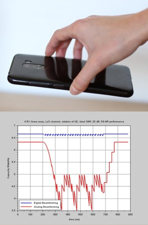
This pick up the phone scenario is one of the trickiest situations to handle when using mmWave radio frequencies ; the communication between the mobile device and the base station is done using antenna arrays and beams. During the time you pick up the phone from the table (it takes roughly 0.5 seconds) the communication direction between the antennae in the smartphone and the base station changes a lot, thus in order to maintain the communication with the base station the processor in the device needs to perform beam-tracking.
In traditional mmWave radio system solutions using analog techniques, the beamforming (signal combining) is made in the analog domain close to the antennae, using phase shifters, and a combined signal is fed to the digital processor performing the beam-tracking. Since the processor only sees the combined signal, it needs to guess how to change the signal combining once it recognizes that the received signal strength has started to deteriorate. If the direction towards the base station changes very quickly, the beam tracking will always be lagging, with the result being that the device will not be able to receive the signal from the base station and hence not be able to transmit the signal in the right direction to the base station. Very low data rates (causing lagging), or even a dropped connection, is the result you will see on your smartphone.
Using a mmWave digital beamforming solution, the beamforming (signal combining) is performed in the digital processor after the digital processor has estimated the direction of the incoming signals. Using optimized beam-tracking algorithms, implemented in the processor, the signal can still be tracked even in this challenging scenario, and the performance will therefore not deteriorate as in the case using analog beamforming.
BeammWave has developed smart algorithms, optimised for a sustainable and scalable digital beamforming solution, thereby handling all kinds of challenging scenarios and minimizing the risk of lagging and performance degradation when the device operates using mmWave communication.
Did you know that people typically check their smartphones over 250 times per day? 80% check their phone when they wake up, 70% use their phone when in the restrooms and 40% look at their phone when driving despite it being illegal in most countries.
From such data one can understand that with more than 6.6 billion smartphone users in the world, looking on average 250 times a day on the smartphone, the way one can hold the phone may be a gigantic issue.
Regardless of whether you are standing, sitting, laying down or jumping you expect the device to have contact with the Internet so that you can use your favourite application whenever you desire.
For communication on radio frequencies below 6 GHz, i.e. the radio frequencies used in 3G and 4G today, a traditional antenna design with one or a few antennae, mainly at the top of the phone, is sufficient to handle all kinds of weird ways to hold a mobile device.
The introduction of communication in the mmWave radio frequency range in 5G, giving a tremendous increase of capacity in the network as well as enabling VR and AR applications requiring Gb/s data rates, comes with some challenges for smartphone applications. For instance, putting a finger on the antenna may drop the radio signal strength 100-1000 times (20-30 dB) so even a world class single antenna design placed at the top of the smartphone may not be sufficient. Also, if you are lying in your bed streaming your favourite series and having the phone in landscape mode, your hand will block the single antenna. Therefore you need a multi-antenna solution, not only to direct (beamform) your signal towards the base station, but also to have a sufficient number of antennae that are not blocked by your hand regardless of how you hold the smartphone!
Classical multi-antenna design for mmWave in handheld devices is based on distributing a number of antenna panels using analog beamforming in the phone. This is a very bulky solution, restricting the number of panels to 2 or 3 (placed at the top and on one or two of the sides). However, this will still not solve the hand blocking problem for all of the ways in which you can hold the smartphone, leading to a risk of a bad connection causing lagging or – even worse – a dropped connection.
To solve the problem, one needs a distributed antenna approach based on digital beamforming. Instead of having 2-3 antenna panels with 4 antennae, one needs 8-12 antennae distributed around the device with the capability to operate each antenna and radio transceiver independently of each other in order to combat the hand blocking problem.
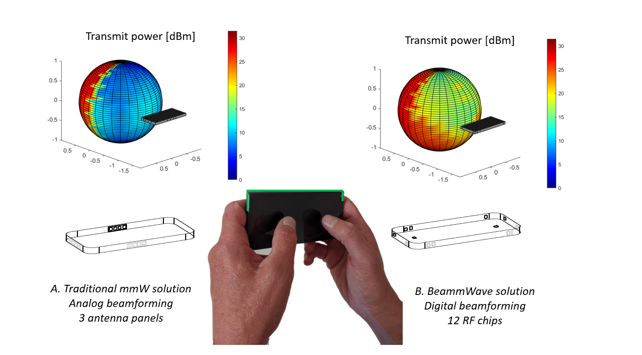
Figure text: (A) shows a traditional mmWave solution for smartphones, with 3 antenna panels, each having 4 antennae. When the phone is in landscape mode, 2 out of 3 antenna panels are blocked giving bad signal quality in many directions (blue colour).
(B) shows BeammWave’s digital beamforming solution with 12 RF chips (i.e. 12 antennae) distributed around the phone. In landscape mode there will always be sufficient antennae which are free from hand blocking thereby giving good signal quality in all directions (red to green colour).
BeammWave understands all aspects of the mobile device challenges with mmWave communication and can deliver a sustainable, high performance, scalable digital beamforming solution that is optimised for handheld devices, thus making it possible to maintain a high speed connection to the Internet regardless of how you may want to hold your smartphone!