What about the future? What are the new applications? And can we really use this to communicate with exoplanets?
How can operators benefit from digital beamforming? What is the capacity gain and why does it work so much better?
Drilling into the hart of the matter for BeammWave! Digital beamforming – to-be-or-not-to-be?
What is mmWave and how do you do beamforming?
The mmWave frequency range is highly suitable for sensing and radar purposes due to the short radio wavelength enabling localization and positioning in the mm to cm range. Joint sensing and communication is being discussed, where a communication system not only communicates but also senses the environment and basically uses mmWave radar for the detection and positioning of objects.
Traditionally when designing analog or hybrid beamforming solutions for mmWave the design has been targeting a single application. A certain antenna panel/array has been designed for a certain purpose, such as a handheld device, and if another mmWave transceiver architecture is needed for another application that needs more antennae, such as a fixed wireless access point, or a small base station, another larger antenna panel has typically needed to be designed.
The 5G-NR mmWave communication devices range from a simple IoT device, via smartphones and fixed wireless access points, to devices for non-terrestrial communication as well as base stations. Designing different antenna panels with analog beamforming solutions for each of these use cases comes with a cost.
It would be an advantage to develop a scalable beamforming solution covering several of the use cases above, thereby reducing the development cost and enabling innovation of potential not-yet-known applications (possibly having almost unlimited bandwidth) as is the case in the mmWave radio spectrum.
Fortunately a digital beamforming architecture where one integrates the radio transceiver (RF) chip and antenna in a single encapsulation has this scaling possibility. The radio chip comprises the analog front end radio components, including down and upconverters, taking the mmWave radio signal from mmWave radio frequency down to an analog baseband signal on the receiver side and converting the transmitted analog baseband signal to mmWave radio signals on the transmitter side. The analog baseband signals have a bandwidth corresponding to the 5G-NR mmWave bandwidth and therefore are in the range of 100-400 MHz, those signals being easy to route on the PCB to a digital baseband processor.
The above integrated antenna and RF chip, when combined with digital beamforming algorithms that are implemented in the digital baseband processor, can be tailored to a flexible amount of antennae. Thus a scalable, low cost mmWave implementation for various use cases can be achieved by just applying as many RF chips as are needed for the particular use case. For instance, if we consider a mmWave IoT device that is only transmitting a small amount of data over short ranges, then it may only need two RF chips, plus associated SW that handles beamforming, to be configured for connection to two antennae to create such a device.
A more complex use case relates to a mmWave smartphone implementation. This needs to solve the challenges associated with handheld devices (these have been discussed in previous posts) and therefore need a distributed antenna architecture with, say, 8-16 Antennas and RF chips, with the corresponding digital beamforming algorithms adapted to that amount of antennae. Considering even more complexity, such as a Fixed Wireless Access Point, then 32-64 RF chips may be needed so as to achieve the desired data rate (several Gb/s).
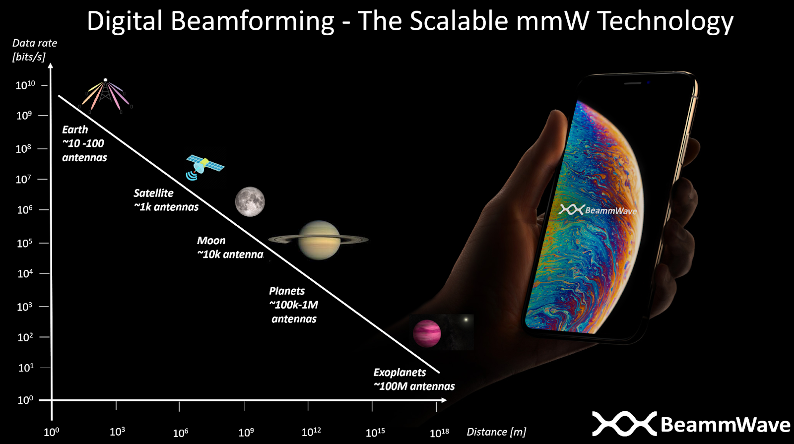
The same set of mmW RF chips are reused for all types of devices. However, in order to meet any requirements for higher transmitting power and better receiver sensitivity, typical for more advanced use cases, then these are solved by adding more RF chips. The level of scaling can also continue to base stations, devices used for non-terrestrial communications such as drones and aeroplanes (requiring 100+ antennae) and to devices communicating with satellites (1000+ antennae). One can even imagine extending the scaling idea of digital beamforming radio architectures to inter-planetary and interstellar communication, where the number of antennae in these cases need to be in the range of hundreds of thousands to hundreds of millions of antennae. However, there might be some challenges with the 5G latency requirements in the communication that need to be solved as well 
BeammWave develops a scalable digital beamforming architecture enabling the mmWave mass market on earth as well as in the sky.
We have in our previous posts shown the advantages with digital beamforming over analog beamforming from a performance point of view. Then one may ask; why hasn’t digital beamforming in mobile devices happened yet?
Well, if you ask people in the field, they will say that a digital approach has way to high power consumption due to the need of entire transceiver chain for all antennas whereas an analog approach only requires single transceiver chain due to that the beamforming is done in the analog domain at the front-end receiver using phase-shifters. Well, this might have been the truth in the past but let us check the case with the current state of the art technology.
Starting with the analog phase-shifters, which comprises switches and various physical routing of traces on the PCB used in order to make sure of coherent combining of the signal received or transmitted from the respective antenna. Passive phase shifters come with a loss of 8-10 dB to the already weak radio signal received by the antenna. That signal power loss needs to be compensated by a high gain Low Noise Amplifiers (LNA) on the receiver side and a high gain Power Amplifier (PA) design on the transmitter side. Such high gain high LNAs and PAs consume a significant part of the total power consumption in the radio receiver.
A digital beamforming architecture performs the combining in the digital domain and therefore the LNA and PA design can be more relaxed for digital architectures saving significant amounts of the power consumption.
Another important factor is that it is commonly believed that the analog-to digital and digital-to analog converters (ADC,DAC) need to be designed in the same way for both digital and analog beamforming, and since a digital beamforming requires an ADC/DAC pair for each antenna while the analog one only requires a single pair of ADC/DAC the power consumption must be N times larger for these components if N antennas is used. Furthermore, ADC/DAC has also in the past been a very power-hungry component and that (today erroneous) fact is still in many people’s mind in the field.
In fact, the power consumption for ADC/DACs especially when using 4-8 bits resolution, which is what is sufficient from a handheld device point of view, is nowadays, with evolving chip technology, on par with other radio components. Furthermore, which might at a first glance be a bit surprising, is that the number of bits needed for digital beamforming architectures can be reduced with 1 – 2 bits compared to an analog beamforming implementation due to the inherent converter quantization noise suppression made by combining the receiver streams after the ADC instead of before the converters as in the analog case! This relaxes the power consumption for the ADCs in digital beamforming solutions with 50-75% compared to the ADC needed for the analog solution!
By understanding and utilizing these facts together with a careful digital beamforming system design, BeammWave can deliver a sustainable and scalable digital beamforming solution with power consumption on par or better than current analog beamforming solutions for mobile devices! For further information please check out our white paper on The Power Efficient Architecture for 5G on mmWave Frequencies.
One of the key features of cellular communication is mobility – this allows a mobile terminal to move around between cells while maintaining an uninterrupted connection to the network. Mobility is important in mmWave communication too and particularly so if mmWave communication is to be successful in offloading traffic from increasingly loaded sub 6 GHz carrier frequencies.
Current radio architectures used in mobile terminals for 5G-NR mmWave communication rely on analog beamforming. In analog beamforming the mobile terminal can only transmit or receive in one direction at a time. Therefore, when searching for neighbouring cells, the mobile terminal is allowed to carry out beam sweeping in which it uses up to 8 different beams for detecting signals from every possible direction around it. This translates into the neighbour cell detection time being up to 8 times longer than if the mobile terminal had been capable of receiving from multiple directions at the same time. The same principle applies to signal strength measurements on beams in the serving cell i.e. the mobile terminal is granted additional time for carrying out beam sweeping. Analog beamforming thus results in a less responsive system, where handover or beam change may take a longer time than desired and therefore may lead to reduced end-user experience (end-user throughput, latency, power consumption) and overall system performance (system throughput, capacity). Additionally, it may lead to the mobile terminal dropping the mmWave connection and falling back to sub 6 GHz where capacity is scarce.

In contrast, digital beamforming allows the mobile terminal to receive from any direction without first having to conduct beam sweeping, and further, to receive from more than one direction at a time, if needed. Therefore, digital beamforming results in a far more responsive system than when analog beamforming is used, leading to better end-user experience and stronger overall system performance by the mobile terminal being connected to the best cell and the best beam at any given time.
BeammWave’s mobility algorithms utilise the above mentioned beam scanning and beam tracking advantages, along with a digital beamforming architecture, to thereby enable a robust mobility operation for mmWave communication.
5G, as well as previous generations of cellular communication, relies on standardized communication protocols for the interactions between mobile terminal and the base station. With new and evolved features, and support of higher data rates, the complexity of the standards has increased for each new generation of mobile communication.
Previous generations of cellular communication standards are using frequencies up to about 3 GHz, for which reliable communication can be maintained using one or a few omnidirectional antennas on the terminal side. With the introduction of NR frequency range 2 (24-71 GHz) (FR2), also known as mmWave, this is about to change as the radio propagation path loss at higher frequencies calls for beamforming based on multiple antenna elements to achieve sufficient sensitivity on both transmitter and receiver sides.
At a first glance it may seem that the requirements for beamforming in NR FR2 would only affect the radio front-end parts of the modem in a handheld device or the radio units in the base station, and by that only the radio frequency requirements of the 3GPP specifications. However, basically all aspects of the communication protocol for NR are affected when introducing mmWave communication.
The figure below shows a block scheme over the cellular modem part in a multi-RAT 5G-NR smartphone, supporting all communication generations from 2G to 5G. The modem can be partitioned into (1) radio components supporting the sub 6 GHz communication (i.e. all legacy communication 2G-4G and also the sub 6 GHz communication mode (FR1) in 5G), (2) radio components supporting the mmWave communication introduced in 5G-NR, and (3) a baseband processor performing all algorithms needed to process a received radio signal to an information signal in the receiver and generate a radio signal from the transmitted information signal in the transmitter. The figure also shows which parts of the radio blocks and baseband processor algorithms that need to be updated for mmWave communication, such as (with reference to respective 3GPP standardization document number)
- Radio frequency requirements (38.101-2)
- Demodulation performance requirements (38.101-4)
- Radio resource management (38.133)
- Physical channels and modulation (38.211)
- Physical layer procedures for control and data (38.213, 38.214)
- Physical layer measurements (38.215)
- Media access control (38.321)
- Radio resource control (38.331)
As can be seen mmWave communication is not only about radio design but it affects basically all algorithms and procedures in the modem, from the physical layer, up to the RRC layer .
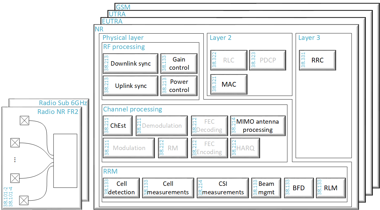
Figure: a block scheme of a modem in a handheld device and corresponding parts affected by mmWave communication.
BeammWave understands all these aspects of the standard and how mmWave will impact the system design in handheld and fixed wireless devices, as well as in base stations, and will deliver a sustainable, scalable digital beamforming solution that enables the mass market for mmWave communication for 5G-NR.